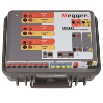
The SMRT43 Smart Grid relay test system is a lightweight, field portable test set capable of testing a wide variety of electromechanical, solid state, and microprocessor-based protective relays, motor overload relays, and similar protective devices.
The SMRT43 has the ability to be manually controlled with Megger’s new Smart Touch View Interface (STVI). The STVI is Megger’s second generation of automatic/semi-automatic manual user interface software. With its large, full colour, high resolution, TFT LCD touch screen, it allows you to perform manual, steady-state, and dynamic testing quickly and easily using the manual test screen, as well as using built-in preset test routines for most popular relays. The STVI displays metered values such as AC and DC Amperes, AC and DC Volts, and time in both seconds and cycles. Depending on the type of test selected, other values may be displayed, such as phase angle, frequency, ohms, watts, VA, or power factor/dissipation factor. Menu screens and touch screen function buttons are provided to quickly and easily select the desired test function. Tests results can be saved to the STVI for download to a USB drive to transfer or print test reports.
For full automatic testing, the SMRT43 can also be placed under full computer control via the Advanced Visual Testing Software (AVTS), or the STVI-software running on a PC. AVTS is a Microsoft Windows XP/Vista/7/8/10 compatible software program designed to manage all aspects of protective relay testing using the Megger SMRT43.
The test system may also be customised by adding the number of voltage-current modules, called VIGEN modules, needed for specific test applications with a maximum of three channels. For example, the SMRT43 with three VIGEN Modules provides complete three-phase testing of three-phase impedance, directional power, negative sequence overcurrent and other devices that require a three-phase four-wire wye connected sources. The fourth voltage channel provides an AC reference/synchronising/polarising voltage, or a DC battery simulator voltage source.